
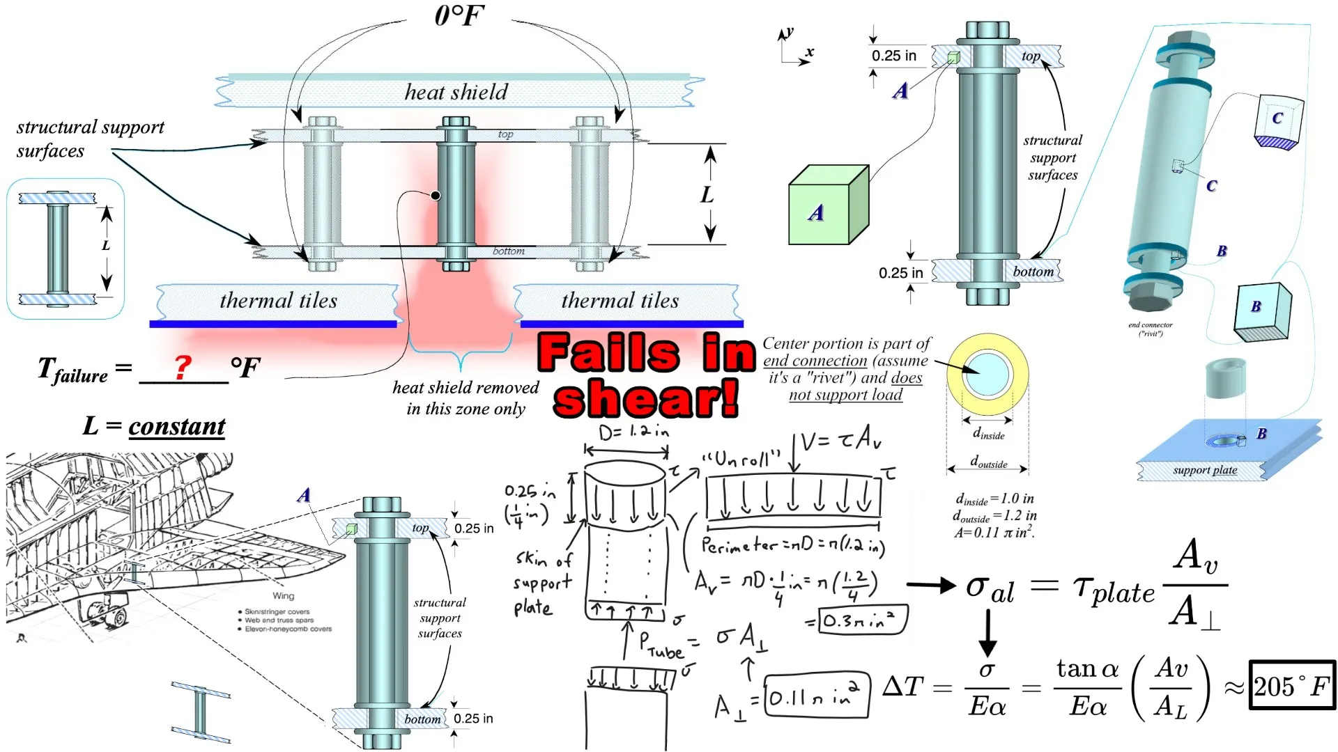
In this video, I solve Problem 1 of the EM 304 test that Dr. Judy Wood gave her students on February 6, 2003, five days after the Space Shuttle Columbia disaster. If a thermal tile is lost, how hot can an aluminum tube held between two rigid support plates get before something fails? I check three candidates: compression in the aluminum tube (442.2 °F), bearing on the plate at the tube end (515.9 °F), and shear in the plate around the tube (205.03 °F). The shear stress in the plate arises due to the compressive stress in the tube that the plate is connected to. Since the temperature of 205 °F is the lowest, the failure occurs first as shear in the plate, even though the corresponding compressive stress in the tube (27.8 ksi) is far less than its strength limit of 60 ksi.
Watch on: Notes · YouTube · Rumble · Odysee · BitChute · Telegram
Timestamps:
- 0:00 Problem 1 of EM 304 on February 6, 2003: Possible cause of failure is the loss of a thermal tile
- 1:01 Problem assumptions: Aluminum tube is heated uniformly while the remaining structure is at 0° F
- 3:26 Given three volume elements to examine the corresponding stresses and temperatures at failure
- 6:20 Material properties for the support plates and aluminum tube
- 9:33 Three questions: Determine maximum temperature of the aluminum tube before failure, first failure location, stress states at the three volume elements, and draw these stress state diagrams.
- 11:17 Location descriptions: Point A is inside the top plate, B is the surface between the plate and tube, Point C is the outer surface of the aluminum tube.
- 12:02 Solution: I used Dr. Judy Wood's solution key and Grok AI's assistance in this solution
- 12:20 Thermal expansion properties: Support plates are idealized as perfectly rigid and non-expanding, while the aluminum tube uses the 2014-T6 aluminum alloy properties.
- 12:38 Strength limits of the plates and tube. Note that ksi = kips per square inch = 1000 psi
- 14:52 Solution to (a): Maximum temperature without failure
- 17:33 The aluminum tube is assumed to be of constant length, which means the thermal expansion displacement is equal to the resulting compressive displacement.
- 20:17 Equation for thermal displacement involving the coefficient of linear thermal expansion
- 22:21 Equation for Young's Modulus and compressive stress
- 24:30 Rearrange to obtain our temperature increase formula (and force that develops in the tube)
- 27:16 Candidate 1: Aluminum tube in compression (point C)
- 29:07 Maximum temperature at failure at point C is 442.2 °F
- 32:04 Candidate 2: Plate bearing at the tube end (point B)
- 34:40 Plates are idealized as rigid and non-expanding, so we have to scale up the temperature of the aluminum tube by the ratio of the plate to tube compressive strength limits and obtain failure temperature of 515.9 °F at point B.
- 35:47 Candidate 3: Shear at the plate connection (point A)
- 37:19 Free body diagram of the shear stress in the plate due to the compressive stress in the tube
- 42:27 "Unrolling" the circular shear stress to obtain a rectangle corresponding to the shear area
- 45:40 By equilibrium, we obtain a formula for the compressive stress in the tube as a function of the shear stress in the plate and the ratio of the shear area to compressive area
- 49:00 Temperature at failure at point A is 205.03 °F
- 53:30 Solution to (b): It fails at point A first, shear in the plate, because its failure temperature is the lowest
- 54:33 Solution to part (c): Stress state at the failure temperature
- 55:46 Obtain compressive stress in the aluminum from the shear stress in the plate using our earlier derived formula, and get 27.8 ksi, which is also the uniaxial compressive stress at point C and bearing stress at point B. This stress is well below the plate and tube allowable compressive stresses
- 59:02 Solution to (d): Volume-element sketches
- 59:38 Note: The "1 + 2" are actually points Dr. Judy Wood gives when grading tests
- 1:03:30 Shear stress diagram needs to have arrows be in equilibrium aka not rotating
- 1:06:02 Summary of the Engineering Logic: Compressive stress in the tube causes failure in shear at the plate, even though the compressive stress is far below its strength limit
Notes and playlists:
- Full video: https://mes.fm/space-shuttle-columbia
- Playlist: https://www.youtube.com/playlist?list=PLEJOImrX4SIc
- https://mes.fm/math
Notes: Problem 1 of EM 304 – Test #1 – February 6, 2003, Solution to Part (a): Maximum temperature without failure, Solution to part (b): Where it fails first, Solution to part (c): Stress state at the failure temperature, Solution to part (d): Volume-element sketches, Summary of the Engineering Logic
Written notes — mirrored from Exam Problem by Dr. Judy Wood: Space Shuttle Columbia Disaster, which has the full video and the complete solution.
Problem 1 of EM 304 – Test #1 – February 6, 2003
Last Saturday (February 1, 2003), the space shuttle Columbia disintegrated during re-entry through the Earth's atmosphere.
One possible cause could be the loss of thermal tiles…


- Assume tiles were lost in the localized zone shown below, exposing just one of the many aluminum stiffening tubes, connected to both the top and bottom framework of the wing.
- Assume the remaining structure is completely insulated from the heat and remains at 0°F.
- Assume the one exposed tube is heated uniformly.
- At 0°F, the aluminum tube is stress free and there are no gaps.
- Heat shields insulate the structure from temperature variations, as shown below.
- Assume the top and bottom of the framework is made of a solid plate.


Material properties:
- L = constant
- Note this is the length of the aluminum tube within the structural support surfaces (support plates) as shown in the earlier figure above.
- Δtmax = 3,000°F (maximum possible)
- From wiki: During re-entry, the thermal protection system (TPS) experienced temperatures up to 3,000 °F (1,648 °C), but had to keep the orbiter vehicle's aluminum skin temperature below 350 °F (180 °C).
Top and Bottom plates:
- αplate = 0.00 με/°F
- Eplate = ∞, G = ∞, v = 0 (rigid)
- τmax = 10.2 ksi
- σmax = 104 ksi (tension)
- σmax = 74 ksi (compression)
Aluminum (2014-T6):
- αal = 12.8 με/°F
- Eal = 10.6 Msi, G = 3.9 Msi, v = 0.34
- τmax = 19 ksi
- σmax = 60 ksi (tension)
- σmax = 60 ksi (compression)
Given the properties above:
(a) Determine the maximum temperature of the aluminum tube without causing failure at point A, B, or C.
- Note: Failure may occur in the plate or the tube.
(b) Where is it most likely to fail first (choose location A, B, or C). Why?
- Justify your answer with calculations.
(c) Using your answer from part (a), calculate the stress state in locations A, B, and C at the failure temperature.
(d) Show these stresses (from part (c)) on each of the volume elements (A, B, and C) provided on above, representing the state of stress at each of the three locations.
Note: Volume elements C, B, and A are provided below.
Location descriptions:
- Point A: zone of material inside top plate
- Point B: surface of plate facing tube end, and surface of tube end facing plate
- Point C: zone of material in outer surface of the aluminum tube.
Solution to Part (a): Maximum temperature without failure
Determine the maximum temperature of the aluminum tube without causing failure at point A, B, or C.
Note: Failure may occur in the plate or the tube.
Let's look at locations A, B, and C in the earlier given diagrams, also shown below.
We are given that the one aluminum tube is exposed and heated uniformly while the top and bottom support plates (and the rest of the structure) stay at 0 °F.
At 0 °F the aluminum tube is stress-free and there are no gaps.
The plates are modeled as rigid (E = ∞, G = ∞, v = 0, α = 0), so the length L of the tube is fixed.
Only the exposed tube wants to expand due to thermal expansion; the rigid plates prevent that expansion, producing compressive force in the tube and equal-and-opposite reactions on the plates.
Failure can occur in the aluminum tube or in the plates (bearing or shear).
Because L is constant:


Candidate 1: Aluminum tube in compression (point C)
If the first failure is aluminum in compression, then the maximum temperature is:

60,000/(10.6*12.8) = 442.217
Candidate 2: Plate bearing at the tube end (point B)
The support plate's compressive allowable stress is given as σmax = 70 ksi.

If the point at B fails, then the compressive stress is greater than 70 ksi.
But we have already checked the point at C, which has a compressive strength of 60 ksi in the aluminum tube, thus the aluminum controls as it would fail before the plate does.
Since the support plates are idealized as rigid and non-expanding, we can't just plug in α = 0 and E = ∞ into the earlier ΔT formula to obtain the temperature at this higher stress.
As the aluminum tube expands due to thermal expansion, this expansion imposes stress on the support plate as well.
Thus, we can obtain the maximum temperature that the support plate will fail at by simply scaling up our earlier maximum temperature by the ratio of the compressive strength of the support plate to the aluminum tube.

Note again that the aluminum tube at point C will fail before this temperature is reached at point B in the support plate.
70/60 * 442.217 = 515.9198
Candidate 3: Shear at the plate connection (point A)
First note that we are told to assume that the "remaining structure is completely insulated from the heat and remains at 0 °F".
The skin of the wing, aka the support plate, is not affected by the temperature, but it is affected by the thermally expanding aluminum tube.
This thermal expansion of the aluminum tube causes shear stress on the support plate, at the point A.

Thus, by equilibrium:

Recall that the maximum allowable compressive stress in the aluminum is 60 ksi, while the maximum allowable shear stress in the support plate is 10.2 ksi.
Thus we can now obtain the corresponding temperature increase of the aluminum tube that would cause the support plate to fail in shear.

10,200/(10.612.8)(0.3/0.11) = 205.0279
This is the lowest temperature rise!
Therefore the maximum allowable temperature of the tube is 205 °F.
Solution to part (b): Where it fails first
Where is it most likely to fail first (choose location A, B, or C). Why?
Justify your answer with calculations.
The three candidate temperatures are approximately:
- A: 205 °F
- B: 442 °F
- C: 516 °F
Thus the failure occurs first at point A, which is shear in the support plate at the tube connection.
Solution to part (c): Stress state at the failure temperature
(c) Using your answer from part (a), calculate the stress state in locations A, B, and C at the failure temperature.
We can use our earlier equation relating aluminum compressive stress to the plate shear stress:
Note that Dr. Judy Wood used the stress-strain-temperature equation to obtain this corresponding compressive stress, both choices work.

10.2*(0.3/0.11) = 27.8182
At point C (outer surface of the aluminum tube), we have uniaxial compression of 27.8 ksi.
At point B (interface): the same compressive force acts as bearing stress on the plate and as axial stress on the tube end.
Because the force is limited by shear capacity at A, the bearing stress is well below the plate allowable (70 ksi).
At point A (inside the plate), the stress state is pure shear at the maximum allowable shear stress in the plate, which was given as 10.2 ksi.
Solution to part (d): Volume-element sketches
(d) Show these stresses (from part (c)) on each of the volume elements (A, B, and C) provided below, representing the state of stress at each of the three locations.
Note: Volume elements C, B, and A are provided below.
On the provided volume elements, the stresses at ΔT = 205 °F are shown below:
Note: The "1 + 2" are actually points Dr. Judy Wood gives when grading tests.


Summary of the Engineering Logic
Because the plates are rigid, the aluminum tube develops compressive stress linearly with temperature.
The connection, however, can transmit only a limited shear force before the plate fails in shear.
That force limit is reached at only 205 °F, which is well before the aluminum itself reaches its 60 ksi compressive yield.
Hence the first failure is shear at the plate-to-tube interface (point A).
- Watch on: 3Speak · YouTube · Rumble · Odysee · BitChute · Telegram
- Full video and written notes: Exam Problem by Dr. Judy Wood: Space Shuttle Columbia Disaster
- Playlist: Space Shuttle Columbia Disaster YouTube playlist
- More math: mes.fm/math
Originally posted on the Hive blockchain →